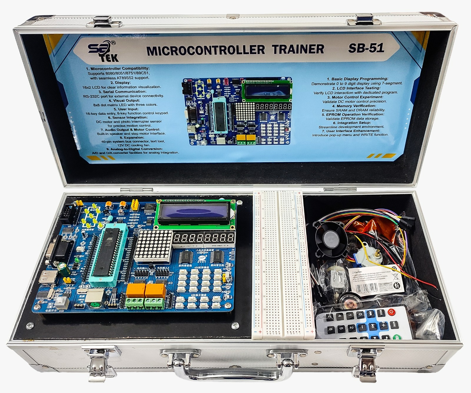
01. SYSTEM OVERVIEW: The SB-51 is a microcontroller trainer from SB-TEK built around an AT89S52-compatible 40-pin MCU, with seamless support for the 8080/8051/8751/89C51 family. It packages display, input, sensor, motor-control, and analog conversion peripherals onto a single board, and ships in a carrying case together with a breadboard, cooling fan, stepper motor, jumper leads, remote control, and other lab accessories — giving students a complete, self-contained microcontroller lab kit. A 16×2 LCD, an 8×8 tri-color dot-matrix LED, and an 8-digit 7-segment display cover the trainer's visual-output experiments, while a 16-key data-entry keypad and an 8-key function keypad handle user input. Sensor and motor-control experiments are supported by a DC motor with photo-interrupter sensor and a step-motor interface, and an on-board RS-232C port and 40-pin system bus connector provide external device connectivity and expansion.
02. CORE HARDWARE SPECIFICATIONS
Parameter Specification
Microcontroller Compatibility Supports 8080 / 8051 / 8751 / 89C51, with seamless AT89S52 support
Display 16×2 LCD for clear information visualization
Serial Communication RS-232C port for external device connectivity
Visual Output 8×8 dot-matrix LED with three colors
User Input 16-key data-entry keypad, 8-key function control keypad
Sensor Integration DC motor and photo-interrupter sensor for precise motion control
Audio Output & Motor Control Built-in speaker and step-motor interface
Expansion 40-pin system bus connector, text tool, 12V DC cooling fan
Analog-to-Digital Conversion A/D and D/A converter facilities for analog integration
03. COMPONENT & MODULE OVERVIEW
Category Components / Modules
Core & Programming • AT89S52-compatible 40-pin MCU socket
• RS-232C serial port
• USB port
• Crystal oscillator
• Reset button
• Power ON/OFF switch
Display Modules • 16×2character LCD
• 8×8 tri-color dot-matrix LED
• 8-digit common-cathode 7-segment display
Input Devices • 4×4 matrix keypad (16-key data entry)
• 8-key independent function keypad
Memory • On-board SRAM / DRAM
• EEPROM module
Motor & Relay Outputs • Two relay output channels
• Two DC-motor input terminals
• Step-motor interface
Analog I/O A/D and D/A converter section for analog integration
04. KEY FEATURES
• Wide MCU compatibility — 8080/8051/8751/89C51 family with seamless AT89S52 support
• Combined visual-output suite: 16×2 LCD, 8×8 tri-color dot-matrix LED, and 8-digit 7-segment display on one board
• Dual keypad input — 16-key data entry plus 8-key function control
• Integrated motion-control experiments via DC motor, photo-interrupter sensor, and step-motor interface
• Built-in speaker for audio-output experiments alongside motor control
• On-board A/D and D/A conversion facilities for analog integration exercises
• 40-pin system bus connector and RS-232C port for expansion and external device connectivity
• Complete accessory kit — breadboard, jumper leads, cooling fan, stepper motor, and remote control — housed in a protective aluminum carrying case
05. GUIDED EXPERIMENTS
Experiment Objective
1. Basic Display Programming Demonstrate 0-to-9-digit display using 7-segment.
2. LCD Interface Testing Verify LCD interaction with a dedicated program.
3. Motor Control Experiment Validate DC motor control precision.
4. Memory Verification Ensure SRAM and DRAM reliability.
5. EPROM Operation Verification Validate EPROM data storage.
6. Integration Setup Streamline the development environment.
7. User Interface Enhancement Introduce pop-up menu and WRITE function.
06. ACCESSORIES & PACKAGE CONTENTS
• Main SB-51 trainer board (AT89S52-compatible)
• Full-size solderless breadboard
• Multi-color jumper wire / ribbon cable set
• 12V DC cooling fan
• Stepper motor
• Infrared remote control
• Piezo buzzer / speaker module
• Assorted component parts bag (connectors, hardware, etc.)
• Aluminum carrying case with printed feature/experiment reference panel