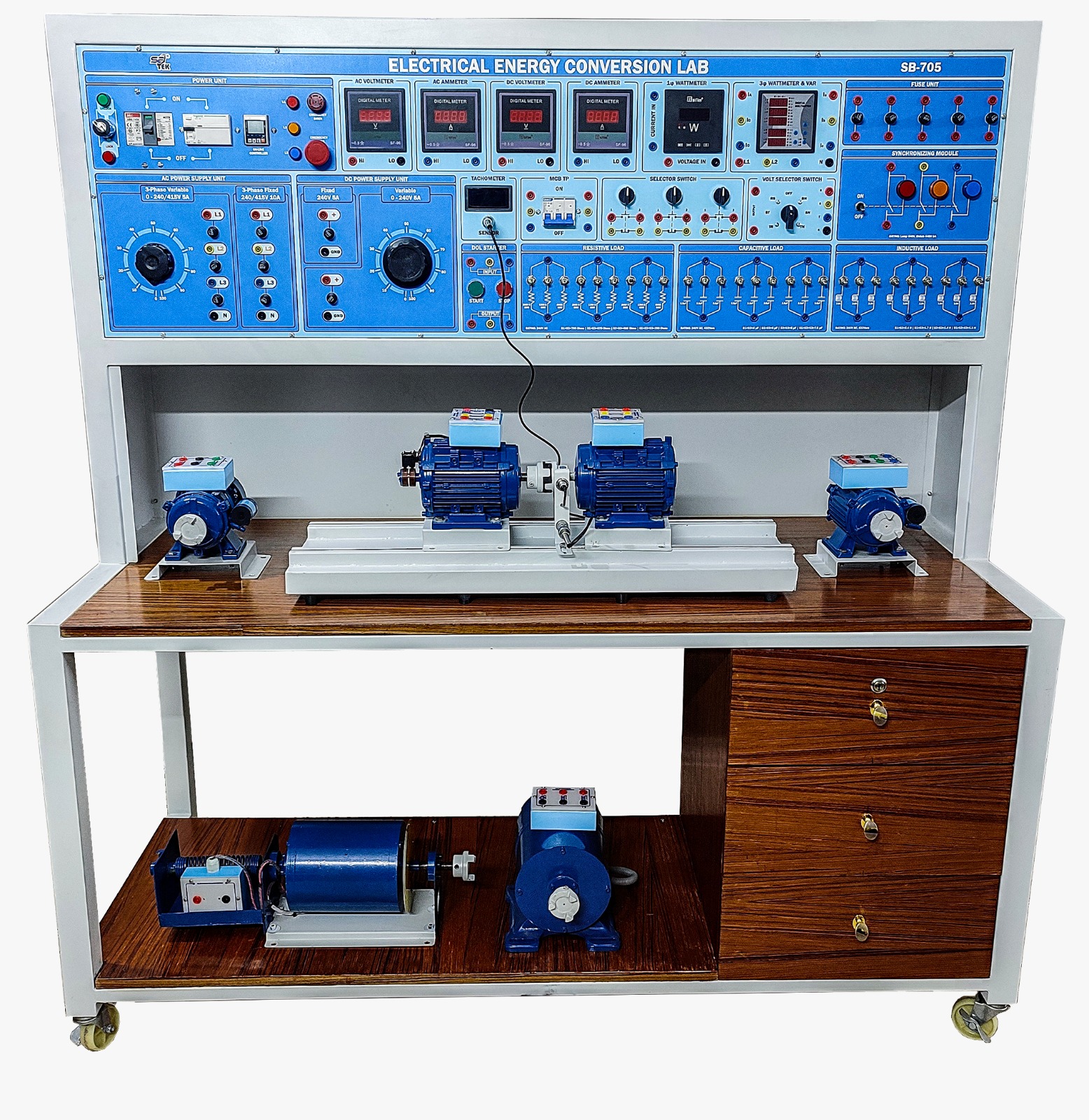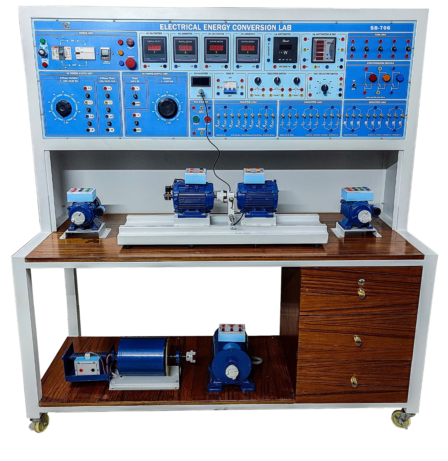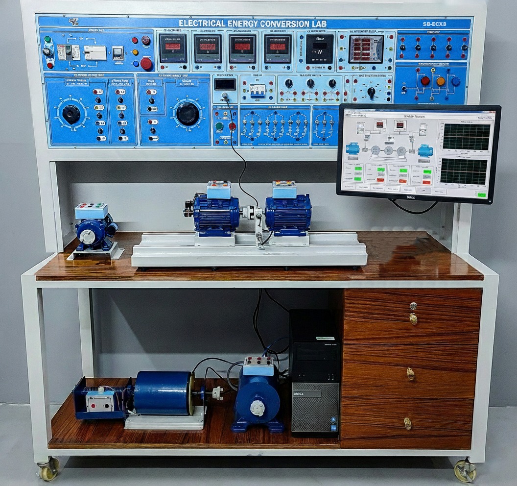
OVERVIEW: The SB-ECX3 Electrical Energy Conversion Laboratory from SB-TEK is an advanced, SCADA-supervised training system for teaching electrical energy conversion principles in engineering laboratories. It integrates AC & DC power supplies, a variety of motors and generators, programmable loads, and digital instrumentation with a real-time Data Acquisition System (DAS) and Advanced SCADA Software Suite (ASCDA). Developed in compliance with European Union Directives (CE, EMC, LVD, RoHS), the SB-ECX3 allows students, instructors, and researchers to perform hands-on experiments with full data logging, monitoring, fault simulation, and analysis, mimicking industrial-grade energy conversion systems.
KEY FEATURES:
• SCADA-supervised laboratory system with single-line diagram (SLD) interface and live monitoring.
• Real-time data acquisition of voltage, current, power, frequency, reactive power, power factor, and rotational speed.
• Multiple AC and DC machines: 3-phase induction motors, 3-phase synchronous motors/generators, DC motors/generators (shunt, series, compound)), universal motors, shaded pole, capacitor start/run motors.
• Integrated AC & DC variable and fixed power supplies with protection and programmable outputs.
• Switchable resistive, inductive, and capacitive loads, including dynamic (motor) loads.
• Advanced synchronization module with synchroscope for generator-to-grid studies.
• SCADA-enabled fault simulation, event logging, and experiment replay for enhanced learning.
• Emergency stop, interlocks, and visual/audio indicators for full lab safety compliance.
SYSTEM SPECIFICATIONS:
Power Unit:
• Key-lock controlled main switch, MCCB, RCCB, and emergency protection system.
• Fully integrated with SCADA-controlled power monitoring and trip indication.
AC & DC Power Supply Unit:
• Input: 415V AC, 3-phase, 4-wire.
• Variable AC Output: 0-240/415V AC, 5A ±5%
• Fixed AC Output: 415V AC, 10A ±5%
• Variable DC Output: 0-240V DC, 5A ±5%
• Fixed DC Output: 240V DC, 5A ±5%
• Overcurrent, overvoltage, and short-circuit protection integrated with SCADA alarms.
• SCADA-enabled series/parallel power control with individual layer protection monitoring.
Digital Meters & Data Acquisition:
All electrical parameters are digitally monitored and logged through SCADA DAS:
• DC Voltmeter/Ammeter: 0-600V / 0-50A
• AC Voltmeter/Ammeter: 0-600V / 0-50A
• Digital Wattmeter: 0-3000 W per phase
• Digital Tachometer: 0-6000 rpm
• Multi-function parameters via SCADA:
Line-to-Neutral Voltage (VL-N).
Line-to-Line Voltage (VL-L).
Phase Current (A) and Total Current (?A).
Active Power (W) per phase and Total (?W).
Reactive Power (var) per phase and Total (?var).
Apparent Power (VA) per phase and Total (?VA).
Power Factor (COS?).
Frequency (Hz).
Real-time energy consumption (Wh).
Motors & Generators:
The SB-ECX3 includes a wide range of AC and DC machines, all fully integrated with the SCADA system for real-time monitoring and control.
3-Phase Squirrel Cage Induction Motor: Rated 1 HP, 1400 rpm, 415V, 1.5A. SCADA monitors voltage, current, power, efficiency, and speed during starting and loaded operation.
3-phase Synchronous Motor/Generator: Rated 1 HP, 1400 rpm, 415V, 1.5A; Generator rating 622 VA, 1400 rpm, 0.17A. The motor supports synchronization studies with SCADA-based voltage, frequency, and phase angle monitoring.
DC Motor/Generator (shunt, series, compound):
Motor rated 175W, 1500 rpm, 240V, 1.1A; Generator rated 120W, 1500 rpm, 240V, 0.5A. SCADA tracks load performance, efficiency, and energy output.
3-Phase Wound Rotor Motor:
Rated 175W, 1500 rpm, 415V, 0.48A. Rotor resistance start and performance parameters are logged via SCADA.
Shaded Pole Motor:
Rated 220–240V AC, 5A, 50Hz, 1400 rpm. SCADA captures voltage, current, and power characteristics.
Capacitor Start Motor:
Rated 175W, 1400 rpm, 220V, 50Hz. Starting performance, current peaks, and power factor monitored in real-time.
Capacitor Run Motor:
Rated 175W, 1415 rpm, 220V, 1.3A. SCADA monitors running performance and efficiency.
AC/DC Universal Motor:
Rated 175W, 8000 rpm, 240V, 1.5A. Speed, current, and power monitored with SCADA control.
Digital Tachometer:
The Digital Tachometer indicates motor rotation speed either in a clockwise or counterclockwise direction. The measured speed is automatically indicated on a five-digit display and is updated every second to enable measurement of acceleration and deceleration. Coupling to the shaft of a motor is accomplished through a rubber tip attached to the Digital Tachometer. The optical sensor can also be used with a reflective tape to read motor speed. Designed to fit comfortably in either the right or left hand, the tachometer is constructed to withstand years of rugged use.
Specifications:
Direction of Rotation: CW and CCW.
Speed Range: 0.5-19 999 r/min (Contact Tacho) / 5-99999 r/min (Photo Tacho).
Accuracy: 0.05% + 1 digit.
Resolution (up to 999.9 r/min): 0.1 r/min.
Resolution (1000 r/min and above): 1 r/min.
Sampling Time: 1 s (for speeds > 60 r/min).
Display: 5 digits.
Memory Hold Time: 5 minutes after measurement.
Power Four 1.5 V AA cells.
Accessories Included Rubber contact tip, rubber contact ring, instruction manual, storage case, reflective tape, and batteries.
Timing Belt:
The Timing Belt is a high-quality industrial synchro-cog timing belt made of rubber whose teeth exactly mesh with the geared pulley fitted on the shaft of all 0.2 kW EMS machines. The Timing Belt is supplied in a fixed length appropriate for coupling two adjacent EMS machines together without slippage between them.
Specifications:
Physical Characteristics
Pitch 9.5 mm (0.375 in)
Pitch Length 819 mm (32.25 in)
Number of Teeth 86
Dimensions (Width) 12.7 mm (0.5 in)
Net Weight 0.1 kg (0.2 lb)
Thyristor Speed Controller:
The Thyristor Speed Controller is designed to control the speed of the DC Motor/Generator in both the open-loop and closed loop modes of control. The Thyristor Speed Controller module contains a thyristor
single-phase bridge rectifier installed in a full-height EMS module. Speed control of the dc motor is achieved by varying the firing angle of the thyristors. In the open-loop mode of control, the firing angle is set manually using a potentiometer, while, in the closed-loop mode, it is set by a controller which compares the motor armature voltage to a voltage reference set by the user. The mode of control is selectable using a toggle switch.
Other parameters that can be controlled using the Thyristor Speed Controller include ramp control, IR compensation, and current limit. These controls are accessible directly on the faceplate of the module.
Schematic symbols and their electrical interconnections are silk-screened on the faceplate of the module. Components are terminated by 4 mm color-coded safety sockets where student access is required.
Specifications
Power Requirements: 120-240 V, 5 A, 50/60 Hz
Variable DC Bus: Voltage 0-100 V, Current 3 A.
Fixed DC Bus: Voltage 100 V, Current 1 A
Physical Characteristics:
Dimensions (H × W × D) 308 × 287 × 450 mm (12.1 x 11.3 x 17.7 in).
Net Weight 5 kg (2.2 lb).
Three phase full voltage stater:
The Three-Phase Full-Voltage Starter is designed to start the Four-Pole Squirrel-Cage Induction Motor and Three-Phase Wound-Rotor Induction Motor directly from the ac power network. The module consists of a three-pole magnetic contactor with a variable overload relay. The components are interconnected to the line and load terminals. A power-on pilot lamp and I and O push-buttons are also mounted on the module faceplate. The auxiliary contacts of the main contactor can be accessed for use as an interlock in control circuits. Connections are made through 4 mm color-coded jacks.
Specifications:
Motor Power 0.2 kW
Line Voltage 208 V ac, 3-Phase
Full Load Current 1.1 A
Reduced Voltage Starting Time 20 s
Physical Characteristics:
Dimensions (H x W x D) 156 x 287 x 440 mm (6.1 x 11.3 x 17.3 in)
Net Weight 4.4 kg (9.7 lb)
Shipping Weight 6 kg (13.2 lb)
Manual dc motor stater:
The Manual DC Motor Starter can be wired as either a three- or four-point dc starter to be used in conjunction with the DC Motor/Generator, Model 8211. The module has a fitted, manually operated handle for variable resistance starting. When it is in the full-run position, the handle is held in place by an electromagnet. In the event of field loss, the holding electromagnet is de-energized and the starting handle is returned to the off position by a stiff spring.
Specifications:
Motor Power 0.2 kW
Line Voltage 120 V dc
Armature Starting Current 3 A
Full Load Current 3 A
Maximum Field Current 0.4 A
Physical Characteristics:
Dimensions (H x W x D) 154 x 287 x 440 mm (6.1 x 11.3 x 17.3 in)
Net Weight 5.9 kg (13 lb)
Shipping Weight 7.5 kg (16.5 lb)
Synchronizing Module|:
The Synchronizing Module is a power control device enclosed in a half-size EMS module. The Synchronizing Module is mainly used to synchronize two ac generators. It can also be used to determine the phase sequence in three-phase circuits. The synchronizing Module has three indicator lamps indicating the relative voltage difference between two circuits. The brightness of the indicator lamps increases with the voltage difference between the two circuits. The Synchronizing Module has a three-phase switch mounted on the module front panel. This three-phase switch is a triple-pole, single-throw switch. Each phase leg of the three-phase switch is protected against over currents and short-circuits by a thermal-magnetic circuit breaker.
Specifications:
Each Phase 240 V – 2 A ac
Light Bulbs 130 V – 2.6 W – BA9S
Circuit Breakers 2 A
Parameter Value:
Physical Characteristics
Dimensions (H x W x D) 154 x 287 x 410 mm (6.1 x 11.3 x 16.1 in)
Net Weight 3.6 kg (7.9 lb)
Three phase full voltage stater:
The Three-Phase Full-Voltage Starter is designed to start the Four-Pole Squirrel-Cage Induction Motor and Three-Phase Wound-Rotor Induction Motor directly from the ac power network. The module consists of a three-pole magnetic contactor with a variable overload relay. The components are interconnected to the line and load terminals. A power-on pilot lamp and I and O push-buttons are also mounted on the module faceplate. The auxiliary contacts of the main contactor can be accessed for use as an interlock in control circuits. Connections are made through 4 mm color-coded jacks.
Specifications:
Motor Power 0.2 kW
Line Voltage 208 V ac, 3-Phase
Full Load Current 1.1 A
Reduced Voltage Starting Time 20 s
Physical Characteristics:
Dimensions (H x W x D) 156 x 287 x 440 mm (6.1 x 11.3 x 17.3 in)
Net Weight 4.4 kg (9.7 lb)
Shipping Weight 6 kg (13.2 lb)
Three-Phase Rheostat:
The Three-Phase Rheostat module consists of three rheostats mounted on a common shaft directly controlled by a single knob on the module faceplate. The rheostats are electrically interconnected in a four-wire wye configuration and each leg is protected from over-current conditions by a thermal-magnetic circuit breaker.
The module is mainly used for speed control of a Three-Phase Wound-Rotor Induction Motor, this module can also be used for other applications where a variable power resistor is needed.
Specifications:
Resistance (line-neutral) 16 ?
Total Power 192 W
Maximum Current (per phase) 2 A
Physical Characteristics:
Dimensions (H x W x D) 154 x 287 x 440 mm (6.1 x 11.3 x 17.3 in)
Net Weight 4.9 kg (10.8 lb)
Shipping Weight 6.5 kg (14.3 lb)
Dynamometer:
A dedicated dynamometer is integrated with the system to measure torque, speed, and mechanical power output of motors. Dynamometer readings are directly interfaced with SCADA, allowing real-time performance analysis, efficiency calculation, and load testing of all machines.
Resistive, Inductive & Capacitive Loads:
Resistive Load: 252 W / 240V / 50Hz.
Inductive Load: 252 VAR / 240V / 50Hz.
Capacitive Load: 252 VAR / 240V / 50Hz.
All loads monitored and controlled via SCADA software, with real-time power, current, and PF visualization.
Switching & Control Devices:
Direct Online (DOL) Starter Unit, Circuit Breaker Unit, Push & Selector Switch Units.
AC 220V Indicator Lamps connected to SCADA for visual status monitoring.
SCADA logs all switching operations with time-stamped event records
Connectors & Accessories:
Male/Female Main Power Connectors.
Connecting Probes with SCADA test point integration.
Neon Tester.
Fuses: 5A, 10A, 15A.
Comprehensive English experimental manual with SCADA step-by-step instructions.
PC & SCADA Configuration:
Dedicated SCADA Workstation for DAS & Control:
Processor: Intel Core i7-11700 / i7-11700K, 8 cores / 16 threads, 5.0 GHz Turbo.
RAM: 32 GB DDR4-3200 (expandable to 64 GB).
Storage: 1 TB NVMe SSD (OS, SCADA software, database, logs).
Monitor: 27? Full HD IPS; dual-monitor recommended for mimic & data analysis.
Communication Ports: USB, Serial (RS-232/RS-485), Ethernet (Modbus/IEC 61850 support).
UPS: 1 kVA, 20–30 min backup for safe SCADA shutdown.
SCADA Integration (ASCDA Software Suite)
Single-Line Diagram (SLD) interface with live motor, generator, and load status.
Motor & Generator Control: Start/Stop, direction, load selection, speed & torque monitoring.
Data Logging & Event Recording: Voltage, current, power, energy, frequency, PF, speed, torque.
Fault Simulation: Line, load, motor, generator faults; duration programmable via SCADA.
Trending & Analysis: Real-time graphs of active/reactive/apparent power, PF, THD.
User Roles: Instructor mode (full control), Student mode (restricted), Admin mode.
Exportable Data: CSV, Excel, or SQL database for research & lab reports.
Experiments (SCADA-Enhanced)
AC/DC Power Supply Test & Calibration.
Three-Phase Motor Starting using DOL Starter.
3-Phase Squirrel Cage Induction Motor: Performance Analysis & Logging.
DC Shunt Motor: Performance & Efficiency Analysis.
Capacitor Start Motor: Starting Performance Analysis.
Capacitor Run Motor: Performance Monitoring.
Synchronous Motor: Synchronization & Stability Studies
AC/DC Universal Motor Performance Analysis.
Shaded Pole Motor: Voltage, Current & Power Analysis.
3-Phase Wound Rotor Motor: Rotor Resistance Control & Load Testing.
Synchronous Motor/Generator: Power Generation & Synchronization.
DC Motor/Generator: Power Generation Analysis.
Load Testing & Efficiency Analysis of Motors.
Fault Simulation and Event Recording.
Power Factor, THD, and Harmonics Analysis.
Learning Outcomes
• Understanding AC/DC energy conversion and motor-generator behavior.
• Real-time SCADA-based monitoring of voltage, current, power, PF, and frequency.
• Performance analysis of different types of motors and generators.
• Synchronization and power generation studies.
• Load control, fault analysis, and event logging using advanced SCADA.
• Power factor improvement, efficiency evaluation, and energy metering.
Standard Features
• Modular, compact, and mobile console design.
• Emergency stop, interlocks, and audible alarms.
• Full European compliance: CE, EMC, LVD, RoHS.
• Comprehensive SCADA-based experimental manual.
• Integrated digital meters, DAS, and SCADA logging for modern laboratory training.