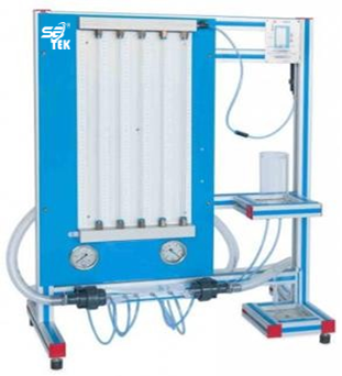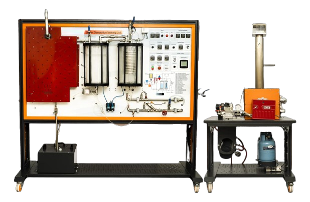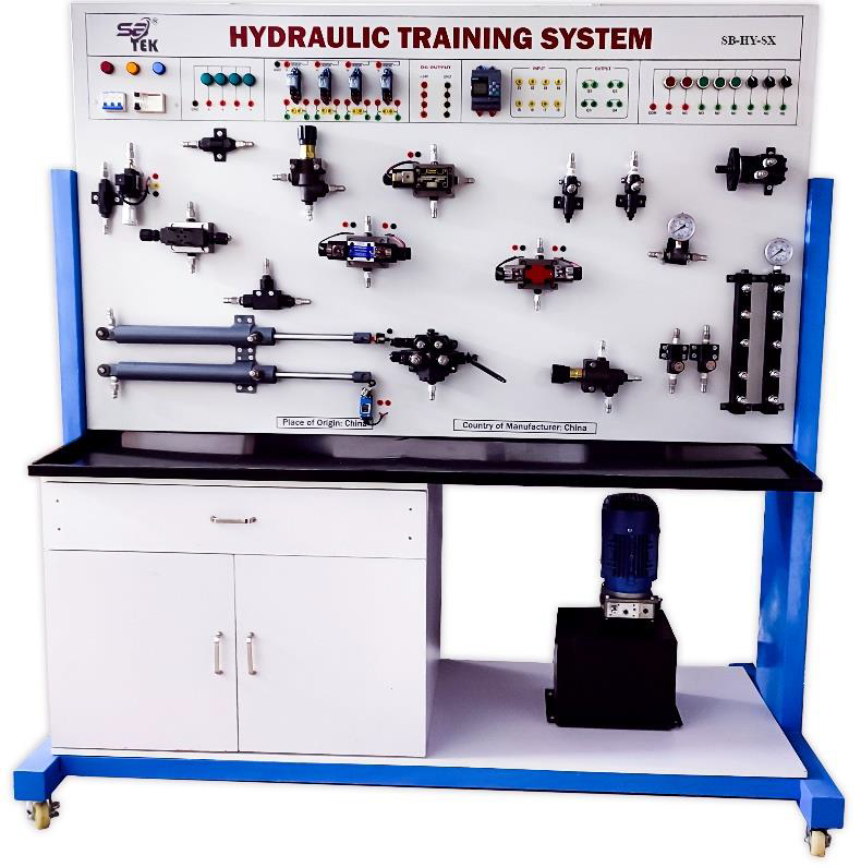
Features: The electro-hydraulics training system provides basic physical principles of hydraulics and electro hydraulics, as well as function and use of electrohydraulic control component. Topic covered: Become familiar with hydraulic pumps. Design of simple electrohydraulic controllers. Design, function and use of electrohydraulic components. Design, function and use of electrical switches, limit switches and relays. Basic logic functions and latch circuits. Systematic troubleshooting and fault rectification.
The Training System Consists of following Component:
The training system equipped with following items along with others:
1. 2-way flow control valve (Min. 1 Nos.): Operating pressure: 50 to 70 MPa. Max. Permissible pressure: min. 12 MPa. Pressure balance: 0.5 to 0.6 MPa.
2. 4/2-way solenoid valve, spring return (Min. 1 Nos.): Operating pressure: 6 MPa. Max. Permissible pressure: min. 12 MPa. Power rating: 6.5 W •Voltage: 24 V Dc.
3. 4/2-way double solenoid valve, detecting (Min. 1 Nos.): Operating pressure: 6 MPa. Max. Permissible pressure: min. 12 MPa. Power rating: 6.5 W. Pulse length: min. 80 msec.
4. 4/3-way solenoid valve, mid-position closed (Min. 1 Nos.): Operating pressure: 6 MPa. Max. Permissible pressure: min. 12 MPa. Power rating: 6.5 W. Voltage: 24 V Dc.
5. Shutoff valve (Min. 1 Nos.): Operating pressure: 6 MPa. Max. Permissible pressure: min. 12 MPa. Actuation: Manual.
6. Mounting kit for cylinders (Min. 1 Nos.).
7. Differential double-acting cylinder (Min. 2 Nos.): Operating pressure: 6 MPa. Max. Permissible pressure: min. 12 MPa. Piston diameter: around 15-20 mm. Stroke Length: Around 200 mm.
8. One-way flow control valve (Min. 1 Nos.): Operating pressure: 6 MPa. Max. Permissible pressure: min. 12 MPa. Actuation: Manual.
9. Pressure relief valve (Min. 1 Nos.): Operating pressure: 6 MPa. Max. Permissible pressure: min. 12 MPa. Actuation: Manual.
10. Pressure gauge (Min. 2 Nos.): Indicating range: min. 10 MPa. Quality class: 1.6% of the full-scale value. Cushioning: Glycerin. Low leakage oil, self-sealing couplings.
11. Pressure switch, electronic (Min. 1 Nos.): Operating voltage: 15-40 V Dc. Switching current: Max. 2 A. Operating pressure: 6 MPa. Max. Permissible pressure: min. 12 MPa. Measuring range: up to 100 MPa.
12. Weight for cylinder: Approx. 5-10 kg (Min. 1 Nos.).
13. Limit switch, electrical, actuated from the left (Min. 1 Nos.): Voltage: 24 V DC. Contact rating: Max. 5 A. Switching accuracy: 0.2-0.5 mm. Actuation force: min. 5 N.
14. Limit switch, electrical, actuated from the right (Min. 1 Nos.): Voltage: 24 V DC. Contact rating: Max. 5 A. Switching accuracy: 0.2-0.5 mm. Actuation force: min. 5 N.
15. Proximity switch, electronic (Min. 2 Nos.): Operating Voltage: 10-30 V DC. Output current: Max. 100 mA. Switching output: PNP, N/O. Switching status display: LED (yellow).
16. Relay, 3-way (Min. 2 Nos.): Operating Voltage: 24 V DC. Current consumption: 140 mA. Pickup time: 10 ms. Drop-off time: 8 ms. Weight: 0.5 to 1 kg.
17. Non-return valve/Check valve with hose (Min. 1 Nos.): Opening pressure: 0.6 MPa. Tubing length: Approx. 1000mm.
18. Signal input, electrical (Min. 1 Nos.): Voltage: 24 V DC. Contact assembly: 1 open, 1 close. Contact rating: Max. 2 A. Power consumption: 0.48 W.
19. T-distributor (Min. 2 Nos.): Operating pressure: 6 MPa. Max. Permissible pressure: min. 12 MPa.
20. 4-way distributor plate with pressure gauge (Min. 2 Nos.): Indicating range: min. 10 MPa. Actuation: Hydraulically via a Bourdon tube. Connections: 5 low-leakage, self-sealing coupling nipples. Mounting: Via two screws and T-head nuts.
Standard Accessories:
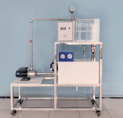
1. Hydraulic power pack with a constant displacement pump:
Input voltage: 220-230V AC, 50/60 Hz. Nominal output: 650W. Delivery rate: 2-3 l/min. Motor: AC (single phase with overload protection). Operating pressure: 6 MPa. Tank Capacity: min 5L
2. Hydraulic oil with HLP 22 to DIN 51524/2 HLP, ISO 6743/4 HM standard (Min 20 Liters)
3. Hydraulic Hoses:
Hose line for quick release coupling (600 mm, 7 pcs).
Hose line for quick release coupling (1000 mm, 2 pcs).
Hose line for quick release coupling (1500 mm, 4 pcs).
4. Digital Multi-meter DC voltage: 400mV to 1000V. AC voltage: 4V to 750V DC current: 400uA to 10A. AC current: 4mA to 10A Frequency response: 40Hz-400Hz Display: 56.5 mm x 36mm.
5. 4mm safety cables.
6. Tabletop Power Supply Unit.
7. Power Supply Unit for mounting frame.
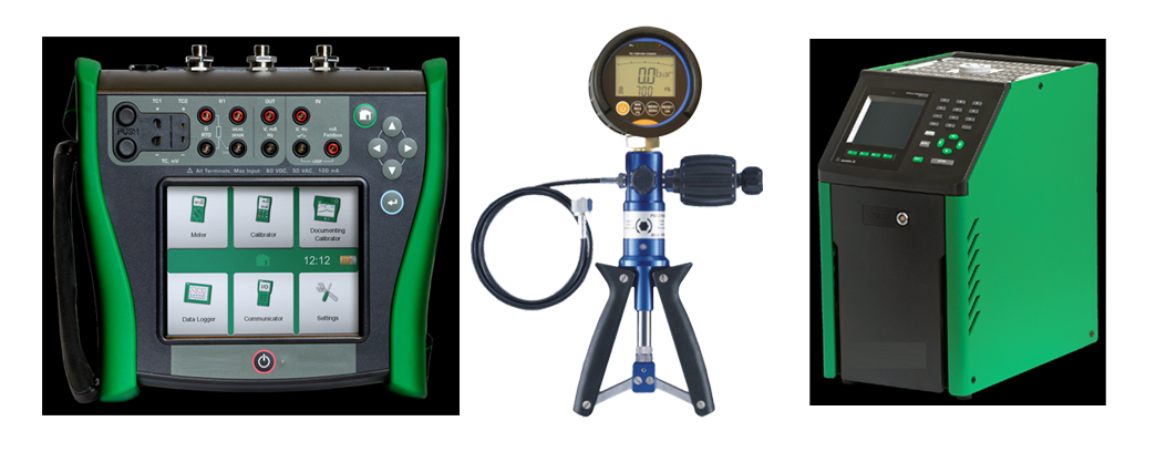
Pressure Gauge Calibrator:
Specification:
Pressure Range: -14 to 1000 psi,-0.97 bar to 690 bar.
Pressure Resolution: 1 psi 0.01 bar
Pressure Accuracy: Positive pressure ± 0.04 % FS. Vacuum ± 0.1 % FS.
Burst pressure: 20000 psi, 1380 bar.
Dimensions (HxWxD: Maximum (5in x 4.5in x 1.5in).
Pressure connection: ¼ in NPT Male.
Housing/Weight: Cast ZNAL 0.56 kg (1.22 lb) with holster.
Display: 5 ½ digits, 16.53 mm (0.65 in) high 20- segment bar graph, 0 to 100%.
Power: Three AA alkaline batteries.
Battery life: 1,500 hours without backlight (continuous on), 2,000 hours at slow sample rate.
Documenting Process Calibrator:
Specifications:
DC Voltage:
Range: 100mV-300V. Resolution (best): 0.00001 V. Best Accuracy, 1 year: 0.02 % + 0.00005V. Input Impedance: >4 M?. Maximum Input Voltage: 300 V.
AC Voltage:
Best Accuracy, 1 year: 0.5 % + 0.002 V. Frequency Range: 40 Hz to 500 Hz. Input Impedance: >4 M ? and <100 Pf. Input Coupling: AC.
DC Current:
Range: 30 mA to 110 mA. Resolution: 1 ?A. Best Accuracy, 1 year: 0.01 % + 5 uA.
Resistance:
Range: 10 ? to 10 k ?. Resolution (best): 0.001 ?. Best Accuracy, 1 year: 0.05 % + 0.0005k?. Open-circuit voltage: 5 V nominal.
Continuity Testing: Range: 25 to 400 ?.
Frequency:
Range: 1 Hz to 500 kHz. Resolution (best): 0.001 kHz.
DC Voltage:
Range: 100mV to 15V. Resolution (best): 1 ?V. Best Accuracy, 1 year: 0.01 % + 0.005 mV.
DC Current:
Range: 0.100 to 22.000 mA. Resolution: 1 ?A. Accuracy, 1 year: 0.01 % + 3 ?A.
Current sink (simulate) Resolution”
Range: 0.100 to 22.000 mA. Resolution: 1 ?A. Accuracy, 1 year: 0.01 % + 7 ?A.
Resistance:
Range: 10 ? to 10 k ?. Resolution: 0.001 ?. Accuracy, 1 year: 0.01 % + 0.010 ?.
Frequency:
Range: Sinewave-0.1 Hz to 10.99 Hz. Squarewave-0.01 Hz to 10.99 Hz. Sine and square-11.00 Hz to 500.00 kHz. Resolution (best): 0.01 Hz. Open Circuit: 26 V ±10 %. Loaded Circuit: 18 V minimum at 22 mA. Output Resistance: 250 ? nominal.
Temperature, Resistance Temperature Detectors (Measure):
100 ? Pt (385):
Range-(-200 to 100)°C. Measure Accuracy-0.07°C. Source Accuracy-0.05°C. Range-100 to 800°C. Measure Accuracy-0.02 % + 0.05°C. Source Accuracy-0.0125 % + 0.04°C.
200 ? Pt (385):
Range-(-200 to 100)°C. Measure Accuracy-0.07°C. Source Accuracy-0.06°C. Range-100 to 630°C. Measure Accuracy-0.02 % + 0.05°C. Source Accuracy-0.017 % + 0.05°C.
500 ? Pt (385):
Range-(-200 to 100)°C. Measure Accuracy-0.07°C. Source Accuracy-0.06°C. Range-100 to 630°C. Measure Accuracy-0.02 % + 0.05°C. Source Accuracy-0.017 % + 0.05°C.
1000 ? Pt (385):
Range-(-200 to 100)°C. Measure Accuracy-0.07°C. Source Accuracy-0.06°C. Range-100 to 630°C. Measure Accuracy-0.02 % + 0.05°C. Source Accuracy-0.017 % + 0.05°C.
100 ? Pt (3916):
Range-(-200 to 100)°C. Measure Accuracy-0.07°C. Source Accuracy-0.06°C. Range(-100 to 630°C). Measure Accuracy-0.02 % + 0.05°C. Source Accuracy-0.0125 % + 0.04°C.
100 ? Pt (3926):
Range-(-200 to 100)°C. Measure Accuracy-0.08°C. Source Accuracy-0.06°C. Range-100 to 630°C. Measure Accuracy-0.02 % + 0.06°C. Source Accuracy-0.0125 % + 0.04°C.
10 ? Cu (427):
Range(-100 to 260)°C. Measure Accuracy-0.2°C. Source Accuracy-0.2°C.
120 ? Ni (672):
Range(-80 to 260 )°C. Measure Accuracy-0.1 °C. Source Accuracy-0.04 °C
Temperature, Thermocouples:
E TYPE: Range: -250 to 1000°C. Measure Accuracy (best)- 0.3°C. Source Accuracy (best)- 0.2°C.
N Type: Range: -200 to 1300°C. Measure Accuracy (best)- 0.5°C. Source Accuracy (best)- 0.5°C.
J Type: Range: -210 to 1200°C. Measure Accuracy (best)- 0.3°C. Source Accuracy (best)- 0.2°C.
K Type: Range: -200 to 1372°C. Measure Accuracy (best)- 0.3°C. Source Accuracy (best)- 0.2°C.
T Type: Range: -250 to 400°C. Measure Accuracy (best)- 0.3°C. Source Accuracy (best)- 0.3°C.
B Type: Range: -600 to 1820°C. Measure Accuracy (best)- 0.9°C. Source Accuracy (best)- 0.8°C.
R Type: Range: -20 to 1767°C. Measure Accuracy (best)- 1.0°C. Source Accuracy (best)- 0.9°C.
S Type: Range: -20 to 1767°C. Measure Accuracy (best)- 0.9°C. Source Accuracy (best)- 0.9 °C.
C Type: Range: 0 to 2316°C. Measure Accuracy (best)- 0.6°C. Source Accuracy (best)- 0.6°C.
L Type: Range: -200 to 900°C. Measure Accuracy (best)- 0.6°C. Source Accuracy (best)- 0.3°C.
U Type: Range: -200 to 900°C. Measure Accuracy (best)- 0.6°C. Source Accuracy (best)- 0.4°C.
Environmental Specifications:
Operating temperature: -10°C to +50°C. Storage temperature: -20°C to +60°C. Dust/water resistance: Meets IP52, IEC 529.
Mechanical and General Specifications:
Size: 136 x 245 x 63 mm.
Weight: 1.2 kg.
Batteries: Li-ion: 7.2V,4400mAh, 30 Wh.
Battery life: >8 hours.
Side port connections: Pressure module connector, USB Connector to interface to your PC, Digital instrument (HART) connector. Data storage capacity: Minimum 1 week of calibration procedures results.
Data log functions:
Measure functions: Voltage, current, resistance, frequency, temperature, pressure. Reading rate: 1, 2, 5, 10, 20, 30, or 60 readings/minute. Maximum record length: 8000 readings (7980 for 30 or 60 readings/minute).
Ramp functions:
Source functions: Voltage, current, resistance, frequency, temperature. Rate: 4 steps/second.
Trip detect: Continuity or voltage (continuity detection not available when sourcing current).
Loop power function:
Voltage; Selectable, 26 V. Accuracy: 10%, 18 V minimum at 22 mA. Maximum current: 25 mA, short circuit protected. Maximum input voltage: 50 V DC.
Step functions:
Manual step: Selectable step, change with arrow buttons. Auto step: Fully programmable for function, start delay, step value, time per step, repeat
General Specification
Display: 480 by 272-pixel graphic LCD, 95 x 54 mm.
Continuity: Beep and the word Short indicate continuity.
Temperature scale.
Safety Compliance: CAN/CSA C22.2 No 1010.1-92, ASNI/ISA S82.01-1994, UL3111, and EN610-1:1993.
Operating Manual: Shall be available with the equipment.
Insulation Resistance Tester:
Specification:
AC / DC voltage measurement
Range: 0 to 299.9 V or higher. 300 to 750 V or higher. Resolution: 0.1 V -1V. Accuracy: ±(3% m.v. + 2 digits). Frequency range for AC: 45 Hz to 65 Hz.
Measurement of Insulation Resistance:
Measuring Standard: EN IEC 61557-2. Range: 0.0 k? to 5.000 T?. Resolution: 0.1 k? to 0.001 T?. Accuracy:±(3% m.v. + 20 digits). Test Voltage: up to 100 V to 5000 V.
Measurement of Leakage Current:
Range: 0 to ILmax. Resolution: m, ?, n. Accuracy: Calculated basing on resistance measurements.
Measurement of insulation resistance in Ramp Test mode:
Range: 0.0 to 4.999 T?. Resolution: 0.1 k? to 0.001 T?. Accuracy:±(5% m.v. + 40 digits).
Measurement of Breakdown Voltage in Ramp Test Function:
Range: 25.0 V to 5.00 kV. Resolution: 0.1 V to 10V. Accuracy (best): ± 5% m.v. ± 4 digits. Protection: IP65. Power Supply: Battery pack, NiMH 9.6 V 2 Ah. Battery charging time: usually 4 h, max.10h.
External power supply: Adapter: 90 V to 264 V, 50 Hz to 60 Hz. Storage temperature: -20ºC to +60 ºC. Operating temperature; -15 ºC to +40 ºC. Humidity: 20% to 90%. Reference temperature; +23 ºC ± 2 ºC. Modular: LCD. Memory of measurement results: 990 cells. Data transmission: USB connection. Quality standard: ISO 9001, ISO 14001, ISO 45001. EMC requirements: EN IEC 61326-1, EN IEC 61326-2-2.
Thermal Imaging Camera:
Specification:
Infrared resolution; 120 x 90 (10,800pixels).
IFOV (spatial resolution): 7.6 mRad, D:S 130:1.
Field of view: 50° H x 38° V.
Minimum focus distance50cm (20 inches).
Focus system: fixed focus.
Data transfer: Mini USB used to transfer image to PC.
Wireless connectivity: Yes, (802.11 b/g/n (2.4 GHz)).
Level and span: Smooth auto and manual scaling.
IR-Fusion technology: Auto Blend continuous 0 % to 100 %.
Display: 3.5" LCD touchscreen (landscape).
Display resolution: 320 x 240 LCD.
Thermal sensitivity (NETD) : 60 Mk.
Frame rate: 9 Hz.
Memory: available Internal 4GB memory.
Image capture, review, save mechanism: Shall be One-handed image capture, review, and save capability.
Image file formats: Non-radiometric (jpeg), or fully radiometric (.is2); no analysis software required for non-radiometric (jpeg) files.
Software: Software available.
Export file formats with Software: JPG, IS2.
Batteries (field- replaceable, rechargeable): Lithium-ion smart battery pack with five-segment LED display to show charge level.
Battery life: ? 5 hours continuous.
Battery charging time: 2.5 hours to full charge.
AC operation: AC operation with included power supply (100 V AC to 240 V AC, 50/60Hz).
Power saving: Automatic Shutdown: 5, 10, 15 and 20 minutes or never.
Temperature measurement:
Range: -20 °C to 400 °C. Accuracy: Target temp at or over 0 °C: Accuracy: ± 2 °C or ± 2 % at 25°C, whichever is the greater.
On-screen emissivity Correction: material table On-screen reflected background temperature.
Compensation: Yes.
Center-point temperature: Yes.
Spot temperature: Hot and cold spot markers.
Standard palettes: available palettes 6: Iron bow, Blue-Red, High Contrast, Amber, Hot Metal, Grayscale.
Infrared spectral band: 8 ?m to 14 ?m (long wave).
Operating temperature: -10 °C to 50 °C (14 °F to 122 °F).
Storage temperature: -20 °C to 50 °C (without batteries).
Relative humidity: 95 % non-condensing.
Safety: IEC 61010-1: Pollution Degree 2.
Electromagnetic Compatibility: EN 61326-1, CISPR 11: Group 1, Class A.
Vibration and shock: 10 Hz to 150 Hz, 0.15 mm, IEC 60068- 2-6; 30 g, 11 ms, IEC 60068-2-27.
Drop: Engineered to withstand 2-meter drop.
Enclosure rating: IP54.
Operating Manual available with the equipment.
Accessories: All standard accessories provided.
Digital Current Clamp meter:
Specification:
Construction Digital, Light weight, Pocket sized, rugged, robust.
AC Current via Jaw: Range: 999.9 A. Resolution: 0.1 A. Accuracy: 2% ± 5 digits (10-100 Hz) Crest Factor (50/60 Hz): 3 at 500 A, 2.5 at@ 600 A, 1.42 at 1000 A.
DC Current: Range: 999.9 A, Resolution: 0.1 A, Accuracy: 2% ± 5 digits.
AC Current via Flexible Current Probe. Range: 2500 A, Resolution: 0.1 A (? 999.9 A); 1 A (? 2500 A). Accuracy: 3% ±5 digits (5-500 Hz), Crest Factor (50/60Hz),
3.0 at 1100 A, 2.5 at 1400 A, 1.42 at 2500 A.
AC/DC Voltage: Range: 1000 V, Resolution: 0.1 V (? 600.0 V); 1 V (? 1000 V). Accuracy: 1% ± 5 digits, mV dc: Range: 500.0 mV, Resolution: 0.1 mV, Accuracy: 1% ±5 digits.
Frequency via jaw: Range: 5.0-500.0 Hz, Resolution: 0.1 Hz, Accuracy: 0.5% ± 5 digits.
Resistance: Range: 60 k?, Resolution: 0.1 ? (? 600 ?), 1 ? (? 6000 ?), 10 ? (? 60 k?), Accuracy: 1% ± 5 digits.
Capacitance: Range: 1000 ?F, Resolution: 0.1 ?F (? 100 ?F), 1 ? F (? 1000 ?F), Accuracy: 1% ± 4 digits.
CAT Rating: CAT III 1000 V, CAT IV 600V.
Backlight: Yes. VFD Low Pass Filter: Yes. Data Logging: Yes. Auto Shutoff: Yes. AC Response: True RMS. Data hold option: Yes. Data display: Min/Max/Avg. Batteries: 2 AA, Alkaline IEC LR6. Jaw opening: 34 mm. Operating Temperature: -10°C to +50°C. Storage Temp: -40°C to +60°C. Safety Conformity: IEC 61010-1, Pollution Degree 2. IEC 61010-2-032: CAT III 1000 V / CAT IV 600 V. IEC 61010-2-033: CAT III 1000 V / CAT IV 600 V. IP Rating: IEC 60529: IP30, non-operating Radio Frequency Certification ID: FCC/IC or equivalent. EMC: International: IEC 61326-1: Portable, Electromagnetic Environment, IEC 61326-2-2 CISPR 11: Group 1, Class A. Accessories: Standard Accessories Supplied.
Industrial Digital Multimeter:
Brand: FLUKE
Model: FLUKE 87V
Country of origin USA.
Specification:
DC Volts: Maximum Range: 1000 V. Maximum Resolution: 10 µV Accuracy: ± (0.05% + 1).
AC Volts: Maximum Range: 1000 V. Maximum Resolution: 0.1 mV. Accuracy: ± (0.7% + 2) True RMS.
AC Bandwidth: 20 kHz with low pass filter; 3 dB @ 1 kHz.
DC Current: Maximum Range: 10 A (20 A for 30 seconds maximum). Maximum Resolution: 0.01 µA Accuracy: ± (0.2% + 2).
AC Current: Maximum Range: 10 A (20 A for 30 seconds maximum). Maximum Resolution: 0.1 µA. Accuracy: ± (1.0% + 2) True RMS
Frequency: Maximum Range: 200 kHz. Maximum Resolution: 0.01 Hz Accuracy: ± (0.005% + 1).
Resistance: Maximum resistance: 50 M? Maximum resolution: 0.1 ?. Accuracy: ± (0.2% + 1).
Capacitance: Maximum capacitance: 9,999 µF. Maximum resolution: 0.01 nF Accuracy: ± (1% + 2).
Duty cycle: Maximum duty cycle: 99.9% Maximum resolution: 0.1%. Accuracy ± (0.2% per kHz + 0.1%).
Conductance: Maximum conductance: 60.00 nS. Maximum resolution: 0.01 nS. Accuracy: ± (1.0% + 10).
Diode: Range: 3 V. Resolution: 1 mV. Accuracy: ± (2% + 1).
Temperature Measurement: -200.0 °C to 1090 °C.
Operating Temperature: –20 °C to + 55 °C.
Safety: EN 61010–1 to 1000 V CAT III, 600V CAT IV.
Display; Digital: 6000 counts updates 4/sec. 19,999 counts in high–resolution mode.
Battery Life: Alkaline: 19,999 counts, updates 3/sec at > 10 Hz ~400 hours typical, without backlight.