Technical Parameters:
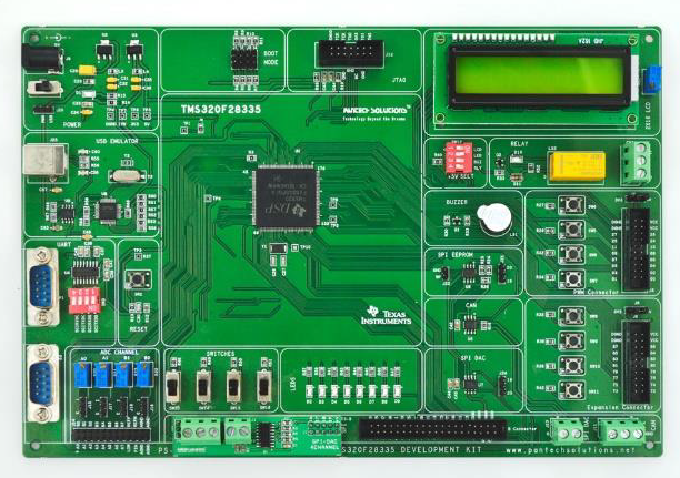
TMS320F28335 DSP development board, is proposed to smooth the progress of developing and debugging of various designs encompassing of High speed 16-bit Architecture from Texas Instrument. The board supports most of the TI components devices and some peripheral options in the Code Composer Studio v4. It integrates on board LEDs, UART, Relays, LCD Display, PWM Motor CONTROL Interface, ADC, SPI DAC, SPI EEPROM and CAN on board XDS100 USB V1 EMULATOR.
MCU:
Texas Instrument TMS320, TMS320F28335 ( 32 Bit CPU )
Memory:
Flash Devices: Up to 256K x 16 Flash bull.
SARAM Devices: Up to 34K x 16 Flash.
BOOT ROM: 8K x 16 ROM.
One Time Programmable Device: 1K x 16 OTP ROM
Clock.
20MHz crystal.
On-Board:
• Peripherals On Board XDS100 USB Emulator V1
• 8 Nos. LEDs
• 4 Nos. Digital Input(Slide Switch)
• 8 Push Switch
• 2×16 Character LCD with back Light
• 4 Nos. Analog Input (Potentiometer)
• 256k SPI EEPROM
• 12 bit SPI DAC
• CAN Interface to study
• 1 Nos. of SPDT Relay
• 3 UART(RS232) interface
• 2 Serial port connector termination
• Buzzer (Alarm)
• 4 Channel 12 bit SPI DAC(Optional)
• Boot Mode Options
Power
• 5V DC- Adaptor,
• Power from USB (+5V) (+3.3V, 800mA)
Connectors:
• 1 Nos. 40 Pin GPIO connector
• 1 Nos.20 Pin PWM Connectors
• 1 Nos.20 Pin Expansion Connectors
• External SPI Connectors
• JTAG (Programming/ Debugging)
• 2 Nos.RS232 Connector (Serial Port)
• External Analog Input Connector
• External
• Relay Input Connector
• Power Connector
• USB Connector
• SPI DAC Connector
• CAN Connector